Test-Driven Development (TDD) is an important software development practice that enables rapid iterations, refactoring, and improved quality. Supporting TDD can be difficult when building Service-Oriented Architecture (SOA) applications, since standard test frameworks often do not have capabilities for performing and validating Web service (WS) calls; invoking Web services depends on running and connecting to a service container; and services and clients often have entirely separate implementations. In this paper we present case studies of two SOA applications we developed, GRIDL and TxFlow. These are distributed, multi-language applications using Web services as the interface between service and client components. They implement Web service and client tests both for verification and validation of the application components and to facilitate the TDD process. Our approach to Web service testing to support TDD is easily reproducible in any SOA application without requiring significant development effort or changes to the software design.
Code is conventionally unit tested by “white-box”testing that calls low-level classes and methods inside a testframework. Web service methods have invocation interfacesthat resemble conventional software methods, but areconsiderably more high-level and complex inimplementation. WS methods are defined as collections ofmessage types and formats, typically in Web ServicesDescription Langauge (WSDL), and are implemented byservice containers that both process Web service messagesand handle communication with remote applications. Whena Web service method is called, the service containerperforms multiple operations, including receiving andparsing the Simple Object Access Protocol (SOAP)request message from the remote application, invokingmethods to process the request, formatting a responsemessage, and sending it to the caller. To realistically test aWeb service, the test must act as a client that connects to aninstance of the service container. In this paper, we describetwo case studies illustrating how we implemented Webservice testing to enable TDD.
Change Data Capture (CDC) is used to identify changesmade to data in a database or data store, so that thesechanges can be propagated across a network to other systemsthat need to know about the changes. Change data capture isused in real-time data warehousingand for event-drivenarchitectures. We can think of several other applicationswhere CDC could be used such as, database replication ormirroring, live data monitoring for statistical analysis andlive monitoring on credit card or telephone records for fraudanalysis and detection
In order toreserve resources for streams in the network several protocolshave been proposed, where they use similar concepts. Forinstance, Stream Reservation Protocol (SRP) [17] defines aset of procedures to reserve network resources for the specifictraffic streams, which are crossing through an Ethernet AudioVideo Bridging (AVB) network. The SRP protocol forcesthe traffic to be registered on the AVB switches throughits path, before being transmitted. Furthermore, a ResourceReSerVation Protocol (RSVP) [18] was proposed to reserveresources for a stream with a specific Quality of Service(QoS) requirement. This protocol operates using an admissioncontrol, which checks whether there are enough resources tosupply the requested QoS requirement. In both protocols, themechanism performs by sending a request through the networkand checking in each node the availability of resources. Theseprotocols provide a support for communicating new reserva-tions in adaptive reservation schemes such as ours.
INTRODUCTION AND BASIC IDEA ABOUT EMBEDDED SYSTEMS.
BRIEF THEORY AND APPLICATION FOR EMBEDDED SYSTEMS TRAINING IN TRICHY.
INTRODUCTION TO RASPBERRY PI /ARDUINO / 8051 Micro-Controller / PIC16F877A / ARM MICROCONTROLLER.
ARCHITECTURE OF ALL DEVICES
COMPARISON OF ARDUINO, ARM, 8051 AND PIC ARCHITECTURES.
THEORY AND PRACTICAL IDEA OF LED INTERFACE.
THEORY AND PRACTICAL IDEA OF SWITCH INTEERFACE WITH MOTOR CONTROL.
PRACTICAL IDEA OF LCD INTERFACE.
THEORY AND PRACTICAL IDEA OF RELAY INTERFACE.
PRACTICAL IDEA OF IR SENSOR AND TEMPERATURE SENSOR INTERFACE.
DESIGN OF VOLTAGE SENSOR AND CURENT SENSOR.
ADC AND DAC INTERFACE.
WIRELESS GSM AND GPS INTERFACE.
SERIAL COMMUNICATION.
THEORY AND PRACTICAL IDEA OF TIMERS AND COUNTER INTERFACES.
THEORY AND PRACTICAL IDEA OF DUST SENSOR AND GAS SENSOR.
PRACRICAL IDEA OF BLUETOOTH AND FINGERPRINT INTERFACE.
Energy optimization is a critical design concern for embedded systems. Combining DVFS+DPM is considered as one preferable technique to reduce energy consumption. There are optimal DVFS+DPM algorithms for periodic independent tasks running on uni-processor in the literature. Optimal combination of DVFS and DPM for periodic dependent tasks on multi-core systems is however not yet reported. The challenge of this problem is that the idle intervals of cores is not easy to model. In this paper, a novel technique are proposed to directly model the idle intervals of individual cores such that both DVFS and DPM can be optimized at the same time. Based on this technique, the energy optimization problem is formulated by means of mixed integrated linear programming. We also present techniques to prune the exploration space of the formulation. Experimental results using real-world benchmarks demonstrate the effectiveness of our approach compared to existing approaches.
Power Intergrated is an Engineering Design Services Company. We currently focus on end to end IC Design Services for IoT, Mobile, NextGen Automobile & SMAC(Social,Mobile,Analytics,Cloud) technologies. We provide solutions to building System On Chips involving both Digital & Analog design.
Power Integrated Solutions, the innovators in Commercial, Electronics Products, Engineering Lab Equipment’s and IEEE & NON-IEEE Based projects, project center in trichy. Our service offers for the complete product development cycle. Our team has more than 10+ year experience in the field of embedded based application designing, product development, project training and course training so.We have also done more than 3000 projects based on Electronic,Electrical,Computer Science,Power Electronics and Power System.In the world, there is a strong demand from industry for engineers who have implementing new technologies for a task.Project Center in Trichy is a design company that works closely with its technical customers to achieve results as fast and as cost effectively as possible With a highly skilled and experienced team of engineers, we provide a broad range of electronic design skills and resources to your project, as it is needed. This gives the project manager the flexibility and control to optimize the project for fast completion or cost, or to react to the unexpected Specialist Area. Our engineering team is made up of engineers with many years of experience with major engineering companies, taking products from concept through to production.
Authentication require two or more factors: “something only the user knows”, “something only the user has” and “something only the user is”. The factors must be validated by the other party for validation to occur. In debit cards authentication mechanisms which can be easily cracked using different mechanisms. According to US attorney report at least 7,000 fake identities are used to obtain more than 25,000 credit cards and documented $200 million in losses, but the figure could rise. The present authentication mechanisms use mechanism where we enter our PIN in pos (point of sale) devices where it is vulnerable in case if we have any skimmer devices installed in any one of the component. Sometimes we have to enter OTP (one time password) in card reader, but it’s vulnerable in case of lost or theft of both mobile and card together. In proposed method, GSM mobile service is used provide the security. Lost Debit Card ATM Card Management System When the Debit card is used, Server will request user to enter a password in his/her mobile phone. If the password valid, Server precedes the transaction, if not so, denies it. The proposed solution effectively prevents clone cards and relay attacks on Debit cards using mobile phone authentication through the flash message service. The proposed solution effectively prevents clone cards and relay attacks on Debit cards using mobile phone authentication through the flash message service. This methodology can be implemented with the current system.
Objectives
This web application will provide the ATM CARD for Customer. Customer can register and select the lost and stolen debit card, credit cards get sms from another customer give. Customer can view the alert sms immediately. Admin can manage the whole process.
Existing Solution:
For some debit cards, we do not have any security mechanisms; we just swipe those cards and make the transaction. This system is highly vulnerable for all attacks, now a days security is added to these cards that we have to enter the PIN in card reader, but its vulnerable to relay attack which makes duplicate transactions and may leads the cards to be skimmed when they are swiped on malicious, For few other cards, we have to enter OTP in card reader, but it’s vulnerable in case of lost or theft of both mobile and card together.
Proposed Solution:
In proposed method, flash message mobile service is used provide the security. When the Debit card is swiped at terminal, the transaction information send to visa server through acquirer bank and with an authentication normal procedures. Visa server will request user to enter a password in his/her mobile phone through the mobile network. If the password is valid, Server proceed the transaction towards the card holder bank and checks availability of required amount then flow of the transaction is as usual, if the password is not valid, server denies the transaction and lets the merchant and user to know that the transaction is denied. So this method can resolve three drawbacks in existing system first case if a card is cloned and swiped at some terminal, anyway the request for password to original owner of the card, he/she can know this transaction is not done by them and they can decline the transaction.
Second case, if relay attack happens in a transaction, the user will be requested for password to perform a parallel transaction also, so he/she can avoid duplicate transaction. In third case, if the mobile phone and card are lost together, no one can make any transaction because the password is not known to anyone other than original user
Microsoft has released the first developer preview of .NET 5, its next major release of the .NET family that’s set for general availability in November and allows developers to build native apps that support Windows 10, iOS, and Android devices.
The .NET 5 preview builds on .NET Core 3.0 and 3.1, which were released in the second half of 2019. According to Microsoft, .NET Core 3 has gained the fastest-ever adoption among developers and an additional one million users in the past year.
The release of .NET 5 is important because it further unifies .NET development across the desktop and mobile thanks to its integration of mobile-app building platform Xamarin.
The .NET Core 3 release introduced Windows Forms and Windows Presentation Foundation (WPF) for building desktop apps, Arm64 support, ASP.NET Blazor for building single page applications, and the gRPC RPC framework for connecting services across data centers.
.NET 5 will include ASP.NET Core, Entity Framework Core, WinForms, WPF, Xamarin and ML.NET.
Ahead of the final version of .NET 5, Microsoft has a clear message for developers: “.NET Core and then .NET 5 is the .NET you should build all your NEW applications with.”
“Having a version 5 that is higher than both .NET Core and .NET Framework also makes it clear that .NET 5 is the future of .NET, which is a single unified platform for building any type of application,” said Scott Hunter, director of program management at Microsoft .NET.
The first preview includes support for Windows Arm64 and the .NET Core runtime, while the second preview will include an SDK with ASP .NET Core but not WPF or Windows Forms, which should arrive in a subsequent preview.
The preview should allow developers to update existing projects by updating the target framework.
The main goals for .NET include providing a unified .NET SDK with a single Base Class Library (BCL) across all .NET 5 applications, with Xamarin moving to the .NET core BCL. Since Xamarin is integrated into .NET 5 the .NET SDK will support mobile.
It also enables native applications to support multiple platforms including Window Desktop, Microsoft Duo (Android), and iOS.
Microsoft’s ongoing work on Blazor should also mean web application support across platforms, including browsers, on mobile devices and as a native desktop application for Windows 10 and Windows 10X.
In the future .NET 5 will also allow for high-performance cloud applications, better support for containers in the runtime, and support for HTTP3.
Hunter is urging developers to move all .NET Core applications to .NET Core 3.1 in anticipation of .NET 5’s release in November.
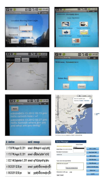
Present android-based location and message sharing system asks to input the personal information which fails to protect the privacy of information, has no centralized database which is causing the problem of data management and portability, and one main drawback is unable to have a secured two way communication between webserver and android based application. And this Android-based Location and Message Sharing System (ALMSS) is proposed for solving above mention problem. The proposed system uses Java programming language for android mobile user application, PHP programming language as webserver, MySQL as external database to store the data, JSON as intermediary between android platform and webserver and uses symmetric cryptography while communicating between android device and webserver which finally assures the protection of information.codeshoppy
Today’s age is the world of technologies, where lots of inventions and discoveries have made everyone to rely on the use of latest technology. Knowingly or unknowingly we are taking the benefit of the technology. Today one can share information with others using the communication technology. One can know what is happening in different parts of the world within a click. It is possible due to the development in the internet services through which one can share the information with the rest of the world. Internet has brought revolution in the field of communication. One can use internet for various purposes depending upon the nature of work. But the main uses of the internet in these days are sharing of information. The main application of internet is web services where internet plays an important role. Another useful development in the technology is the mobile devices. The use of mobile devices is increasing day-by-day. Many improvements have been made, such as faster processors and better battery life, have enabled notebooks and smartphones to become powerful devices, giving us the ability to completely change the way we work. Today’s mobile devices not only comes with the feature of voice communication and sending/receiving messages but also has the features of Internet, Bluetooth, Image capturing, Video recording, GPS facilities and so on. Various smart phones are available in the market, namely Samsung, HTC, Motorola, Apple iPhone, Android, Blackberry products and so on. Among them, Android has been gaining popularity and its market share in the mobile operating system market is rapidly increasing. According to Gartner (2010) [1], Android is poised to become second worldwide mobile operating system in the nearer future. Using the technology – smart phone and internet, people are sharing information to other people but they are not sure if their information is securely transmitted or not. This paper deals with secure transmission of information with each other. The main drawbacks with the existing android-based location and message sharing systems are as follows: 1)No centralized database due to which there is a problem in management of data, portability problem, updates as well as backup problems etc. 2)Most of the location based social network asks to input the personal information. All the messages are displayed on the screen which has failed to protect the privacy of information. 3)Lack of server centric privacy control method. No security has been maintained during transfer of information between server and device. 4)Most of the application that are based on GPS technology are storing location in their built in database and are unable to use it externally so that it is difficult to trace the current location of the people where they are. The main objective of this paper, on the highest level, is to communicate with a PHP server that stores the information sent through the android device in encrypted form and vice-versa which finally establish a secure two way communication between android device and web server. The main highlight of our work is listed below: 1)Connect with the external database MySQL to maintain a centralized database. For achieving this goal, we will use JSON as an intermediary to send the data from android device and PHP to insert that value to the external database MySQL. 2)Interact with the webserver and maintaining security while sharing location and message. For achieving this goal, we will use two approaches, the information sent by the android application is first stored in a database in encrypted form using JSON and PHP as intermediary and decrypt data while extracting from database. And similar process is followed while sending information from webserver to device. All the data are encrypted while sending and key is needed to decrypt this data before reading from the databaseTo find the current location, trace the path and track the people. For achieving this goal, current location is obtained from GPS enabled android device and is sent to webserver and webserver will display location position and path on the web using the feature of Google Map. This paper is organized as follows: section II introduces some background, including Android Platform, PHP and MySQL, JSON and some security measures taken during location and message sharing, section III describes related works, section IV illustrates the design and operation of ALMSS, experiments are performed on section V, section VI finally draws the conclusion and future works
Due to the security issue of the information send by the user and lack of centralized database in the present scenario, this paper has given approach to develop a secured android-based location and message sharing system. In this paper we have used Java programming language to develop the client side, and used PHP programming language to develop server side with MySQL as external database to store information. In this case we are integrating the concept of symmetric cryptography and all the information has been encrypted before saving to the database. We have tested the system in emulator and finally tested the system successfully in the real life scenario using HTC android smart phone. With the help of GPS enabled smart phone we were able to send the longitude and latitude to the webserver, analyzing the location data from the database and displaying the location and trace path in the web which helps us to know where the client is. And finally we were able to send the message through webserver and android device and vice-versa
In an islanded microgrid where the distributed generators (DGs) capacities are not very large and their output powers are fluctuating, a large capacity installation of energy storage system (ESS) is not ideal method due to its high price. Load control is a preferred control for supply and demand balance. At present, many load controls based on central management system have been proposed to achieve supply and demand balance according to the load capacities or price. However, these existing schemes are not suited for islanded microgrids without central controller. This paper proposes an autonomous control of flexible power electronics loads (FPELs), whose objective is to make the FPELs to automatically participate in supply and demand balance and reduce the response cost with various response prices taken into consideration. Therefore, the proposed control scheme can retain advantages of the traditional distributed load control schemes, while can keep in lower response cost. The effectiveness of the proposed control has been validated via Matlab simulations in islanded microgrid.
SIMULATION VERIFICATIONS
MATLAB/Simulink simulation was used to verify the performance of the proposed control scheme. The microgrid is assumed to be composed of two DG units, one ESS, two fixed loads and two FPELs. The power ratings of two DGs, ESS and two FPELs are 1.5kW, 3kW and 0.725kW, respectively. The detailed circuit and control parameters of simulated system are listed in Table I. With this setup, two cases were considered to test the effectiveness of the proposed control scheme: FPELs participate in the supply-demand balance based on their response capacity and their response cost. Code Shoppy
A. Based on response capacity In this case, the fixed loads and FPELs were connected to PCC at first, where the FPELs were under the traditional load control scheme based on the response capacity. Since the DG units and ESS power generation capacity are more than the loads demand, it can be seen that the DGs and ESS can share the loads, and the FPELs can maintain their normal operation from Fig. 5. At t = 0.4s, fixed load2 was turned on. The total load demands were more than the DGs power generation capacities, the microgrid was therefore in heavy load condition and the ESS must output more power to meet the loads demand, as shown in Fig.5 (a) and (b). Click Here In this case, the FPELs were switched to autonomous control scheme along with the frequency declining and autonomously participated in the supply-demand balance based their response capacity, as shown in Fig. 5 (c). From Fig. 5 (c)-(e), it can be seen that the FPELs can equally share the supply-demand imbalance due to the same response capacity. The microgrid can maintain stable, as shown in Fig. 5 (f)-(g). In this case, the total response cost is 320 units.
B. Based on response cost The simulation was tested again to verified the proposed control scheme, where the FPELs were under the autonomous control based on the response cost. Before t = 0.4s, the simulation results shown in Fig. 6 are same as the case A as shown in Fig. 5. After t = 0.4s, with the connection of fixed load2, the frequency was lower than the preset threshold fLower, as shown in Fig.6 (f). With the local frequency measurement, FPELs were switched to autonomous control scheme and autonomously reduce their power consumption to participated in the supply-demand balance based their response cost, as shown in Fig. 6 (c)-(e). From Fig. 6 (c), it can be seen that the FPEL2 reduced more power consumption than the FPEL1 due to the lower response cost. Therefore, the total is 270 units, which is lower than the response cost in the case A.
This paper describes the solution for monitoring and control of power electronics devices in telecommunication facilities. Centralized monitoring of the power supply system enables monitoring of the operation of all devices in the system, using the same user application. In addition to monitoring of individual devices’ operation, the operation of passive elements, which together with the power electronics devices constitute the power system, is also monitored. With the implementation of derived alarms, such as organized, centralized monitoring increases the reliability of the power electronics system and enables the responsible sector to prevent interruptions in the operation of telecommunication equipment by preventive maintenance.
Managing power electronics devices represents switching on or switching off of monitored devices or modules, starting a capacitive test, and adjusting the operating parameters of the power supply device from the remote monitoring center. It is estimated that with such organized remote monitoring, the total costs of installation and maintenance of the power system can be reduced by 16%. The cost resulting from the interruption of telecommunication traffic as well as the cost of termination of the services due to the unreliable operation of the telecommunication system is not included in the savings’ calculation.
Remote Monitoring Technology (RMT) is one of the key factors for servicing the system. Although servicing has been the subject of intensive research for years, the role of RMT in this field is less explored. [1] Power systems consist of energy converters and elements that connect energy converters to energy sources and energy consumers.
Energy converters convert: •an alternating input voltage in direct output voltage (AC/DC converters), •a direct voltage of one value in the direct voltage of another value (DC/DC converters), •a direct voltage in alternating voltage (DC/AC converters – inverters). In addition to energy converters, the components of the power system are: •assembly of AC distribution: connects energy converters with alternating energy sources (power distribution network or generator), •assembly of DC distribution: Code Shoppy connects energy consumers with basic DC power sources and a spare power source (the most common accumulator). Energy converters and generators are complex devices and usually have a microcomputer which, in addition to monitoring the operation of the device itself, can also have the remote monitoring function.
On the other hand, AC and DC distributions consist of passive elements, so most often there is no monitoring of these elements’ operation. This practically means that it is a realistic situation that no one of the monitored devices sends an alarm to the monitoring sectors, regardless of the power system is defective. In practice, such cases are often noticed, and some of them have been described in previous papers [2-4]. The organization of the power electronics devices’ monitoring through the microcomputer, which is an integral element of energy converters, cannot supervise the power electronics system, but only certain elements. Another problem of the described monitoring approach is that microcomputers used for the control of power electronics devices are not a good solution for power electronics devices’ monitoring. Monitoring is not their basic function, so the data obtained in this way are not reliable. If the data are not reliable, the responsible sectors may make the wrong decisions. Figure 2 shows the shape of the voltage at the output of one AC/DC converter, for which the monitoring device showed that the DC voltage at the output of the converter is 190V, in the range of regular values (187V to 242V)
From the oscilloscope image, it is obvious that the DC voltage at the output of the converter changes within the limits of 50V to 300V and is beyond the permitted limits. The mean value of the voltage measured by the oscilloscope is the same as the value obtained using the microcomputer in the device (190V). However, the shape of the voltage shown on the oscillogram requires the urgent intervention of the monitoring sectors, while the data obtained from the microcomputer indicate that no intervention is needed. Another example is shown in Figure 3. The measurement was done with an oscilloscope with a probe that introduced a 10-drop attenuation on a serial resistor of 10 mΩ.
Practically, the current value per interval is 2A. An example is characteristic because no one monitoring device generates an alarm, no one size is beyond the range of allowed values. However, the system is not correct, because the existence of a large alternate component in the charging current of an accumulator suggests that there is a significant problem in the system operation. As a consequence, the operational autonomy of the spare power supply is significantly reduced.
The mean value of the charging current is within the allowed limits. However, there is an alternating component whose maximum value is greater than 8App. This means that there is a serious problem with the serial resistance between the charger and the accumulator. Resistance can be in the accumulator itself, but also in the connections between the charger and the accumulator. Also, the charger requires additional inspection, because the problem can be caused by large variations in the output voltage of the charger.
This problem does not require urgent intervention. However, if the serial resistance is the problem, the power system has no declared autonomy, and if the charger is the problem, the characteristics of the accumulators will be degraded. It is necessary to inspect the operation of several elements of the power supply system. In order to detect the problem of this type, a serious analysis of the collected data obtained from the monitoring systems, as well as the appropriate expert knowledge and experience in the monitoring sectors, is required. By installing remote monitoring and control systems for power electronics devices – SDNU, it is possible to collect the required data set to help analyze the operation of monitored devices. One solution is to automatically generate messages from monitoring programs that would suggest to monitoring sectors what to do. Such messages are named derived alarms [3].
For the described example, the derived alarm would announce a reduced power supply autonomy and suggest that a capacitive test must be done. Both of the above-described examples were recorded after the installation of a device that has been developed specifically for the monitoring of power electronics devices. A mounted centralized monitoring device recognized the alarm state and generated alarms, but local monitoring of the energy converter did not recognize the alarm state. Due to no match in the measurement results, the competent maintenance sectors requested a determination of the right status. Oscilloscope records confirmed that the only correct solution for monitoring of power electronics devices is the use of a device that has been specifically developed only for the monitoring and control of power electronics devices. Accumulator monitoring systems are also independent systems that have the battery life prediction function based on ambient temperature and the discharge curve monitoring. The battery status is transferred to the operating center to increase the reliability of the power supply. [5] The monitoring centers collect data from microcomputers located in the power electronics devices. The usual solutions are that each energy converters’ manufacturer develops its own monitoring system to monitor the operation of the energy converter. The application software has been written so that only one type of energy converters and from only one manufacturer can be monitored at one point in time. This means that different power electronics devices of different manufacturers cannot be monitored simultaneously on the same monitor. This is not a good solution for maintenance sectors, because while monitoring the operation of one type of device, there may be some major accidents on some other devices. In order to avoid this situation, it is common practice to have a large number of monitors in the maintenance sectors, to monitor the operation of each type of power electronics device. Such a solution is not appropriate, because due to poor transparency, it is really possible that some of the alarms pass unnoticed. There are also standardized protocols (SNNP) that allow monitoring of the different devices’ operation on one monitor, but the data set is limited and used in the main (national) monitoring centers. In these centers, there are no experts dealing specifically with the maintenance of power electronics devices, so it is impossible to perform an analysis of the complete system operation. The data collected through standardized protocols are used to engage responsible maintenance sectors based on receiving alarms, in order to intervene on the object in alarm. In this case, there is no possibility of preventive maintenance, but only corrective maintenance. From the data collected through standard protocols, the cause of the alarm is not visible, but the existence of an alarm is noted and this information is forwarded to the maintenance sectors. In practice, it is common that after obtaining an intervention order, and after going on-site, the responsible maintenance sectors find that they cannot correct the defect, because it is not caused by the operation of the power electronics devices in their jurisdiction.
The paper describes one solution for the organization of remote monitoring and control of power electronics devices. The described solution is optimized for maintenance sectors. All elements in the power electronics system are monitored so that the state of each circuit in the system is reliably known. Data from the microcomputer are also collected if they exist as integral elements of the power supply system. In the monitoring center, all data are displayed on one monitor. In order to improve the efficiency of the maintenance sector, the data are divided into three levels. With monitoring organized in this way, the maintenance sectors, in addition to receiving the alarm from an object, can also determine the cause of the alarm and decide who and when to intervene, in order to eliminate the alarm. In addition to reducing the unnecessary going on-site of the maintenance team, the planned maintenance of the power supply system elements is enabled. It is estimated that with such organized remote monitoring, the costs of servicing and replacing elements in power electronics systems can be reduced by about 60%. Savings are achieved due to the extension of the life of spare power supplies about 27%, as well as due to a reduction of the traveling cost assigned to the maintenance sectors of 34%. The cost resulting from the interruption of telecommunication traffic as well as the cost of termination of the services due to the unreliable operation of the telecommunication system is not included in the savings’ calculation. After ten years of tracking the power systems’ operation and analyzing the data obtained from the remote monitoring and control system SDNU, the above data have collected. This assessment coincides with the assessment of some other companies, such as “MIDTRONICS-Battery Management Innovation”, made for Telecommunication companies in the USA Click Here
Study results.The data directory (data) includes the rawdata of our study along with the results presented in theresearch paper. The data on metrics in three dimensions(General/Structure,ICC, andSecurity) is placed in therespective folder. R scripts for producing final results fromthe raw data in each folder are included accordingly. Eachraw data file is explainedhere, and the purpose of each Rscript is explainedhere. A convenience scriptproduceall.shisincluded underdatafor processing all the raw data at once.Benchmark suites.Our study used two benchmark suites:a suite of 125 individual apps and a suite of 62 apppairs that actually communicate at runtime as quicklytriggered by random inputs from Monkey [4]. The firstsuite can be readily downloaded from Google Play usingour helper scripts. The list of these apps is included (indata/benchmarks/used-benig-apps-droidfax.txt).The second suite is even more worthy of sharing becausefinding a set of apps with dynamically communicating peersis not trivial. android project app ideas 2019 This suite is particularly useful for evaluatingan inter-app dynamic analysis for Android. We have notonly provided the pairs but also the statistics on the ICCsthat linked them at runtime in our study (as detailed indata/benchmarks/app-pair-statistics.html).Characterization metrics.We defined a set of 122 metricsin the three dimensions mentioned above. These metrics havebeen used for discovering new insights into the behavioraltraits of Android apps in our study. Furthermore, they havebeen utilized for developing advanced malware classifiers aswell (based on the behavioral profile, defined by these metrics,of benign apps versus malware) [5]. These metrics (detailedhere) can be used by others for understanding app behaviorsand reused for future studies and techniques.